ASME B16.5 Class 400 Flange
1. Technical Drawings for ASME B16.5 Class 400 Flanges
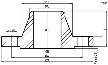
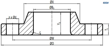
Drawing of ASME B16.5 Class 400 weld neck flange, raised face(RF).
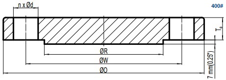
Drawing of ASME B16.5 Class 400 blind flange, raised face(RF).
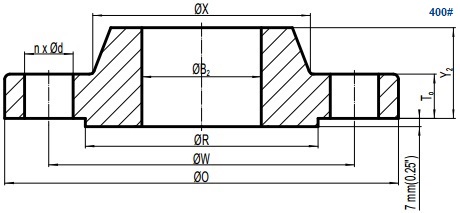
Drawing of ASME B16.5 Class 400 slip on flange, raised face(RF).
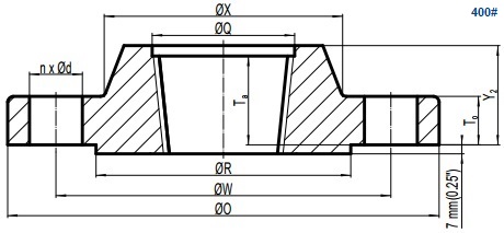
Drawing of ASME B16.5 Class 400 threaded flange, raised face(RF).
Drawing of ASME B16.5 Class 400 lap joint flange.
2. Flange and Bolting Dimensions for Class 400
All dimensions are provided in both mm and inch units. The two unit system shall be used respectively and exclusively. There are 5 types of ASME B16.5 Class 400 flanges: weld neck, blind, threaded, slip on and lap joint. The bolting of Class 400 flanges shall be furnished by stud bolt with nuts. The Class 400 flange has a 7 mm(0.25 inch) raised face which is additional to the minimum flange-thickness. For sizes of 1/2″~3-1/2″, the dimensions of ASME B16.5 Class 400 flange are the same as that of Class 600. Tables below are applicable for flanges with RF end facing. Contact us to obtain the data for other end facings.
| NPS | O mm inch | T mm inch | X mm inch | Ah mm inch | ro mm inch | Q mm inch |
|---|---|---|---|---|---|---|
| 1/2 | 95 3.75 | 14.3 0.56 | 38 1.50 | 21.3 0.84 | 3 0.12 | 23.6 0.93 |
| 3/4 | 115 4.62 | 15.9 0.62 | 48 1.88 | 26.7 1.05 | 3 0.12 | 29.0 1.14 |
| 1 | 125 4.88 | 17.5 0.69 | 54 2.12 | 33.4 1.32 | 3 0.12 | 35.8 1.41 |
| 1-1/4 | 135 5.25 | 20.7 0.81 | 64 2.50 | 42.2 1.66 | 5 0.19 | 44.4 1.75 |
| 1-1/2 | 155 6.12 | 22.3 0.88 | 70 2.75 | 48.3 1.90 | 6 0.25 | 50.6 1.99 |
| 2 | 165 6.50 | 25.4 1.00 | 84 3.31 | 60.3 2.38 | 8 0.31 | 63.5 2.50 |
| 2-1/2 | 190 7.50 | 28.6 1.12 | 100 3.94 | 73.0 2.88 | 8 0.31 | 76.2 3.00 |
| 3 | 210 8.25 | 31.8 1.25 | 117 4.62 | 88.9 3.50 | 10 0.38 | 92.2 3.63 |
| 3-1/2 | 230 9.00 | 35.0 1.38 | 133 5.25 | 101.6 4.00 | 10 0.38 | 104.9 4.13 |
| 4 | 255 10.00 | 35.0 5.75 | 146 5.75 | 114.3 4.50 | 11 0.44 | 117.6 4.63 |
| 5 | 280 11.00 | 38.1 7.00 | 178 7.00 | 141.3 5.56 | 11 0.44 | 144.4 5.69 |
| 6 | 320 12.50 | 41.3 8.12 | 206 8.12 | 168.3 6.63 | 13 0.50 | 171.4 6.75 |
| 8 | 380 15.00 | 47.7 10.25 | 260 10.25 | 219.1 8.63 | 13 0.50 | 222.2 8.75 |
| 10 | 445 17.50 | 54.0 12.62 | 321 12.62 | 273.0 10.75 | 13 0.50 | 276.2 10.88 |
| 12 | 520 20.50 | 57.2 14.75 | 375 14.75 | 323.8 12.75 | 13 0.50 | 328.6 12.94 |
| 14 | 585 23.00 | 60.4 16.75 | 425 16.75 | 355.6 14.00 | 13 0.50 | 360.4 14.19 |
| 16 | 650 25.50 | 63.5 19.00 | 483 19.00 | 406.4 16.00 | 13 0.50 | 411.2 16.19 |
| 18 | 710 28.00 | 66.7 21.00 | 533 21.00 | 457.0 18.00 | 13 0.50 | 462.0 18.19 |
| 20 | 775 30.50 | 69.9 23.12 | 587 23.12 | 508.0 20.00 | 13 0.50 | 512.8 20.19 |
| 24 | 915 36.00 | 76.2 27.62 | 702 27.62 | 610.0 24.00 | 13 0.50 | 614.4 24.19 |
*Ah:hub diameter at the beginning of chamfer for W/N; ro: corner bore radius of lapped flange; Q:minimum counterbore of threaded flange.
| NPS | Y1 mm inch | Y2 mm inch | Y3 mm inch | Ta mm inch | B1 mm inch | B2 mm inch | B3 mm inch |
|---|---|---|---|---|---|---|---|
| 1/2 | 52 2.06 | 22 0.88 | 22 0.88 | 16 0.62 | - | 22.2 0.88 | 22.9 0.90 |
| 3/4 | 57 2.25 | 25 1.00 | 25 1.00 | 16 0.62 | - | 27.7 1.09 | 28.2 1.11 |
| 1 | 62 2.44 | 27 1.06 | 27 1.06 | 18 0.69 | - | 34.5 1.36 | 34.9 1.38 |
| 1-1/4 | 67 2.62 | 29 1.12 | 29 1.12 | 21 0.81 | - | 43.2 1.70 | 43.7 1.72 |
| 1-1/2 | 70 2.75 | 32 1.25 | 32 1.25 | 23 0.88 | - | 49.5 1.95 | 50.0 1.97 |
| 2 | 73 2.88 | 37 1.44 | 37 1.44 | 29 1.12 | - | 61.9 2.44 | 62.5 2.46 |
| 2-1/2 | 79 3.12 | 41 1.62 | 41 1.62 | 32 1.25 | - | 74.6 2.94 | 75.4 2.97 |
| 3 | 83 3.25 | 46 1.81 | 46 1.81 | 35 1.38 | - | 90.7 3.57 | 91.4 3.60 |
| 3-1/2 | 86 3.38 | 49 1.94 | 49 1.94 | 40 1.56 | - | 103.4 4.07 | 104.1 4.10 |
| 4 | 89 3.50 | 51 2.00 | 51 2.00 | 37 1.44 | - | 116.1 4.57 | 116.8 4.60 |
| 5 | 102 4.00 | 54 2.12 | 54 2.12 | 43 1.69 | - | 143.8 5.66 | 144.5 5.69 |
| 6 | 103 4.06 | 57 2.25 | 57 2.25 | 46 1.81 | - | 170.7 6.72 | 171.4 6.75 |
| 8 | 117 4.62 | 68 2.69 | 68 2.69 | 51 2.00 | - | 221.5 8.72 | 222.2 8.75 |
| 10 | 124 4.88 | 73 4.00 | 102 4.00 | 56 2.19 | - | 276.2 10.88 | 277.4 10.92 |
| 12 | 137 5.38 | 79 4.25 | 108 4.25 | 61 2.38 | - | 327.0 12.88 | 328.2 12.92 |
| 14 | 149 5.88 | 84 4.62 | 117 4.62 | 64 2.50 | - | 359.2 14.14 | 360.2 14.18 |
| 16 | 152 6.00 | 94 5.00 | 127 5.00 | 69 2.69 | - | 410.5 16.16 | 411.2 16.19 |
| 18 | 165 6.50 | 98 5.38 | 137 5.38 | 70 2.75 | - | 461.8 18.18 | 462.3 18.20 |
| 20 | 168 6.62 | 102 5.75 | 146 5.75 | 74 2.88 | - | 513.1 20.20 | 514.4 20.25 |
| 24 | 175 6.88 | 114 6.25 | 159 6.25 | 83 3.25 | - | 616.0 24.25 | 616.0 24.25 |
*Ta:minimum thread length of threaded flange; B1:bore diameter of welding neck flange which shall be specified by purchaser.
*B2:bore diameter of slip on flange; B3:bore diameter of lap joint(lapped) flange.
| NPS | W mm inch | R mm inch | d inch | n | do inch | LSRF mm inch | LSRJ mm inch | LTG mm inch |
|---|---|---|---|---|---|---|---|---|
| 1/2 | 66.7 3.75 | 34.9 1.38 | 5/8 | 4 | 1/2 | 75 3.00 | 75 3.00 | 70 2.75 |
| 3/4 | 82.6 4.62 | 42.9 1.69 | 3/4 | 4 | 5/8 | 90 3.50 | 90 3.50 | 85 3.25 |
| 1 | 88.9 4.88 | 50.8 2.00 | 3/4 | 4 | 5/8 | 90 3.50 | 90 3.50 | 85 3.25 |
| 1-1/4 | 98.4 5.25 | 63.5 2.50 | 3/4 | 4 | 5/8 | 95 3.75 | 95 3.75 | 90 3.50 |
| 1-1/2 | 114.3 6.12 | 73.0 2.88 | 7/8 | 4 | 3/4 | 110 4.25 | 110 4.25 | 100 4.00 |
| 2 | 127.0 6.50 | 92.1 3.62 | 3/4 | 8 | 5/8 | 110 4.25 | 110 4.25 | 100 4.00 |
| 2-1/2 | 149.2 7.50 | 104.8 4.12 | 7/8 | 8 | 3/4 | 120 4.75 | 120 4.75 | 115 4.50 |
| 3 | 168.3 8.25 | 127.0 5.00 | 7/8 | 8 | 3/4 | 125 5.00 | 125 5.00 | 120 4.75 |
| 3-1/2 | 184.2 9.00 | 139.7 5.50 | 1 | 8 | 7/8 | 140 5.50 | 140 5.50 | 135 5.25 |
| 4 | 200.0 7.88 | 157.2 6.19 | 1 | 8 | 7/8 | 140 5.50 | 140 5.50 | 135 5.25 |
| 5 | 235.0 9.25 | 185.7 7.31 | 1 | 8 | 7/8 | 145 5.75 | 145 5.75 | 135 5.25 |
| 6 | 269.9 10.62 | 215.9 8.50 | 1 | 12 | 7/8 | 150 6.00 | 150 6.00 | 145 5.75 |
| 8 | 330.0 13.00 | 269.9 10.62 | 1 1/8 | 12 | 1 | 170 6.75 | 170 6.75 | 165 6.50 |
| 10 | 387.4 15.25 | 323.8 12.75 | 1 1/4 | 16 | 1 1/8 | 190 7.50 | 190 7.50 | 185 7.25 |
| 12 | 450.8 17.75 | 381.0 15.00 | 1 3/8 | 16 | 1 1/4 | 205 8.00 | 205 8.00 | 195 7.75 |
| 14 | 514.4 20.25 | 412.8 16.25 | 1 3/8 | 20 | 1 1/4 | 210 8.25 | 210 8.25 | 205 8.00 |
| 16 | 571.5 22.50 | 469.9 18.50 | 1 1/2 | 20 | 1 3/8 | 220 8.75 | 220 8.75 | 215 8.50 |
| 18 | 628.6 24.75 | 533.4 21.00 | 1 1/2 | 24 | 1 3/8 | 230 9.00 | 230 9.00 | 220 8.75 |
| 20 | 685.8 27.00 | 584.2 23.00 | 1 5/8 | 24 | 1 1/2 | 240 9.50 | 250 9.75 | 235 9.25 |
| 24 | 812.8 32.00 | 692.2 27.25 | 1 7/8 | 24 | 1 3/4 | 265 10.50 | 280 11.00 | 260 10.25 |
*LSRF:length of stud bolt for raised face; LSRJ:length of stud bolt for ring joint; LTG:length of stud bolt for male/ female tongue and groove.

Stud bolt with nuts for ASME B16.5 Class 400 flanges.
