ASME B16.5 Class 2500 Flange
1. Technical Drawings for ASME B16.5 Class 2500 Flanges
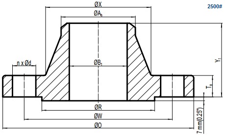
Drawing of ASME B16.5 Class 2500 weld neck flange, raised face(RF).
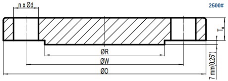
Drawing of ASME B16.5 Class 2500 blind flange, raised face(RF).
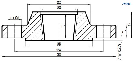
Drawing of ASME B16.5 Class 2500 threaded flange, raised face(RF).
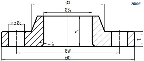
Drawing of ASME B16.5 Class 2500 lap joint flange.
2. Flange and Bolting Dimensions for Class 2500
The ASME B16.5 Class 2500 flanges are available in four types: weld neck, blind, threaded, and lap joint. Threaded flanges 2500# are available with sizes from 1/2″ to 2-1/2″. Others are available with sizes from 1/2″ to 12″. Tables below are applicable to Class 2500 flanges with 7 mm raised face which is additional to the minimum flange thickness.
| NPS | O mm inch | T mm inch | X mm inch | Ah mm inch | ro mm inch | Q mm inch |
|---|---|---|---|---|---|---|
| 1/2 | 135 5.25 | 30.2 1.19 | 43 1.69 | 21.3 0.84 | 3 0.12 | 23.6 0.93 |
| 3/4 | 140 5.50 | 31.8 1.25 | 51 2.00 | 26.7 1.05 | 3 0.12 | 29.0 1.14 |
| 1 | 160 6.25 | 35.0 1.38 | 57 2.25 | 33.4 1.32 | 3 0.12 | 35.8 1.41 |
| 1-1/4 | 185 7.25 | 38.1 1.50 | 73 2.88 | 42.2 1.66 | 5 0.19 | 44.4 1.75 |
| 1-1/2 | 205 8.00 | 44.5 1.75 | 79 3.12 | 48.3 1.90 | 6 0.25 | 50.6 1.99 |
| 2 | 235 9.25 | 50.9 2.00 | 95 3.75 | 60.3 2.38 | 8 0.31 | 63.5 2.50 |
| 2-1/2 | 265 10.50 | 57.2 2.25 | 114 4.50 | 73.0 2.88 | 8 0.31 | 76.2 3.00 |
| 3 | 305 12.00 | 66.7 2.62 | 133 5.25 | 88.9 3.50 | 10 0.38 | - |
| 4 | 355 14.00 | 76.2 3.00 | 165 6.50 | 114.3 4.50 | 11 0.44 | - |
| 5 | 420 16.50 | 92.1 3.62 | 203 8.00 | 141.3 5.56 | 11 0.44 | - |
| 6 | 485 19.00 | 108.0 4.25 | 235 9.25 | 168.3 6.63 | 13 0.50 | - |
| 8 | 550 21.75 | 127.0 5.00 | 305 12.00 | 219.1 8.63 | 13 0.50 | - |
| 10 | 675 26.50 | 165.1 6.50 | 375 14.75 | 273.0 10.75 | 13 0.50 | - |
| 12 | 760 30.00 | 184.2 7.25 | 441 17.38 | 323.8 12.75 | 13 0.50 | - |
*Ah:hub diameter at the beginning of chamfer for W/N; ro: corner bore radius of lapped flange; Q:minimum counterbore of threaded flange.
| NPS | Y1 mm inch | Y2 mm inch | Y3 mm inch | Ta mm inch | B1 mm inch | B3 mm inch |
|---|---|---|---|---|---|---|
| 1/2 | 73 2.88 | 40 1.56 | 40 1.56 | 29 1.12 | - | 22.9 0.90 |
| 3/4 | 79 3.12 | 43 1.69 | 43 1.69 | 32 1.25 | - | 28.2 1.11 |
| 1 | 89 3.50 | 48 1.88 | 48 1.88 | 35 1.38 | - | 34.9 1.38 |
| 1-1/4 | 95 3.75 | 52 2.06 | 52 2.06 | 39 1.50 | - | 43.7 1.72 |
| 1-1/2 | 111 4.38 | 60 2.38 | 60 2.38 | 45 1.75 | - | 50.0 1.97 |
| 2 | 127 5.00 | 70 2.75 | 70 2.75 | 51 2.00 | - | 62.5 2.46 |
| 2-1/2 | 143 5.62 | 79 3.12 | 79 3.12 | 58 2.25 | - | 75.4 2.97 |
| 3 | 168 6.62 | - | 92 3.62 | - | - | 91.4 3.60 |
| 4 | 190 7.50 | - | 108 4.25 | - | - | 116.8 4.60 |
| 5 | 229 9.00 | - | 130 5.12 | - | - | 144.4 5.69 |
| 6 | 273 10.75 | - | 152 6.00 | - | - | 171.4 6.75 |
| 8 | 318 12.50 | - | 178 7.00 | - | - | 222.2 8.75 |
| 10 | 419 16.50 | - | 229 9.00 | - | - | 277.4 10.92 |
| 12 | 464 18.25 | - | 254 10.00 | - | - | 328.2 12.92 |
*Ta:minimum thread length of threaded flange; B1:bore diameter of welding neck flange. B3:bore diameter of lap joint(lapped) flange.
| NPS | W mm inch | R mm inch | d inch | n | do inch | LSRF mm inch | LSRJ mm inch | LTG mm inch |
|---|---|---|---|---|---|---|---|---|
| 1/2 | 88.9 3.50 | 34.9 1.38 | 7/8 | 4 | 3/4 | 120 4.75 | 120 4.75 | 115 4.50 |
| 3/4 | 95.2 3.75 | 42.9 1.69 | 7/8 | 4 | 3/4 | 125 5.00 | 125 5.00 | 120 4.75 |
| 1 | 108.0 4.25 | 50.8 2.00 | 1 | 4 | 7/8 | 140 5.50 | 140 5.50 | 135 5.25 |
| 1-1/4 | 130.2 5.12 | 63.5 2.50 | 1 1/8 | 4 | 1 | 150 6.00 | 150 6.00 | 145 5.75 |
| 1-1/2 | 146.0 5.75 | 73.0 2.88 | 1 1/4 | 4 | 1 1/8 | 170 6.75 | 170 6.75 | 165 6.50 |
| 2 | 171.4 6.75 | 92.1 3.62 | 1 1/8 | 8 | 1 | 180 7.00 | 180 7.00 | 170 6.75 |
| 2-1/2 | 196.8 7.75 | 104.8 4.12 | 1 1/4 | 8 | 1 1/8 | 195 7.75 | 205 8.00 | 190 7.50 |
| 3 | 228.6 9.00 | 127.0 5.00 | 1 3/8 | 8 | 1 1/4 | 220 8.75 | 230 9.00 | 215 8.50 |
| 4 | 273.0 10.75 | 157.2 6.19 | 1 5/8 | 8 | 1 1/2 | 255 10.00 | 260 10.25 | 250 9.75 |
| 5 | 323.8 12.75 | 185.7 7.31 | 1 7/8 | 8 | 1 3/4 | 300 11.75 | 310 12.25 | 290 11.50 |
| 6 | 368.3 14.50 | 215.9 8.50 | 2 1/8 | 8 | 2 | 345 13.50 | 355 14.00 | 335 13.25 |
| 8 | 438.2 17.25 | 269.9 10.62 | 2 1/8 | 12 | 2 | 380 15.00 | 395 15.50 | 375 14.75 |
| 10 | 539.8 21.25 | 323.8 12.75 | 2 5/8 | 12 | 2 1/2 | 490 19.25 | 510 20.00 | 485 19.00 |
| 12 | 619.1 24.38 | 381.0 15.00 | 2 7/8 | 12 | 2 3/4 | 540 21.25 | 560 22.00 | 535 21.00 |
*LSRF:length of stud bolt for raised face; LSRJ:length of stud bolt for ring joint; LTG:length of stud bolt for male/ female tongue and groove.
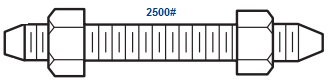
Stud bolt with nuts for ASME B16.5 Class 2500 flanges.
CATEGORY AND TAGS: